555 Timer Schematic : The Three Fives Kit A Discrete 555 Timer Rf Cafe : It can be used in led or flash lamps to turn the lamp on for a specified time.
555 Timer Schematic : The Three Fives Kit A Discrete 555 Timer Rf Cafe : It can be used in led or flash lamps to turn the lamp on for a specified time.. The 555 timer shown above is configured as an astable circuit. Looking for 555 timer circuit board? This tutorial provides sample circuits to set up a 555 timer in monostable, astable, and bistable modes as well as an in depth discussion of how the 555 timer works and how to choose components to use with it. This means that the output voltage is a periodic pulse that alternates between the vcc value and 0 volts. This circuit uses very basic components like 555 timer and 4017 counter.
The breadboard schematic of the above circuit is shown below. As discussed in the above section, the ic is in its standard monostable mode. The 555 ic timer circuit above shows a very straightforward design where the ic 555 forms the central controlling part of the circuit. 555 timer tutorial bundle includes: In monostable mode, the 555 timer outputs a single pulse of current for a certain length of time.
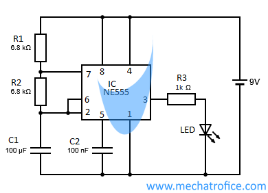
Led Flasher Circuits Using 555 Timer Ic from mechatrofice.com 555 timer circuits (133) browse through a total of 133 555 timer circuits and projects including the timer's datasheet. After about 10 seconds, the led turns off. Lm555 timer 1 features 3 description the lm555 is a highly stable device for generating 1• direct replacement for se555/ne555 accurate time delays or oscillation. All rhythm pulses appear at the out of ic1 and passed to input pin 2 of the 555 timer. We connect a 100μf capacitor to the positive voltage supply and then to pin 2. A popular version is the ne555 and this is suitable in most cases where a '555 timer' is specified. Its name is derived from three 5k ohm resistors,connected in series used in it.the timer ic can produce required waveform accurately. With this information you will learn how how the 555 works and will have the experience to build some of the circuits below.
With one press of the button, the led will light up, then turn off automatically after a predetermined length of time.
In this tutorial we will learn how the 555 timer works, one of the most popular and. After about 10 seconds, the led turns off. This timer circuit is wired as an astable multivibrator to display a seven segment counter with the help of the counter ic cd 4033. The standard timer action of the ic 555 is initiated by introducing a 0 v trigger pulse at pin 2. The general 555 timer circuit schematic at the heart of the circuit is a lm555 ic, which includes 23 transistors, 2 diodes and 16 resistors on a silicon. As discussed in the above section, the ic is in its standard monostable mode. In other words, 555 timer is a circuit which may be connected as a stable or monostable multivibrator. The output will sink or source up to 200 ma. The breadboard schematic of the above circuit is shown below. How to calculate output voltage frequency the frequency is the number of pulses per second. 555 timer ic 555 timer circuits. Daman shah june 5, 2021. The ic can operate in three different modes such as astable, monotstable and bistable, because of which it can be adapted into many types of circuit designs like time delay circuits, pulse generation circuit, oscillator circuit and much more.
555 timer is an industrial standard ic existing from early days of ic. The resistive divider network is used to set the comparator levels. Additional • timing from microseconds through hours terminals are provided for triggering or resetting if • operates in both astable and monostable modes desired. As discussed in the above section, the ic is in its standard monostable mode. We connect a 100μf capacitor to the positive voltage supply and then to pin 2.
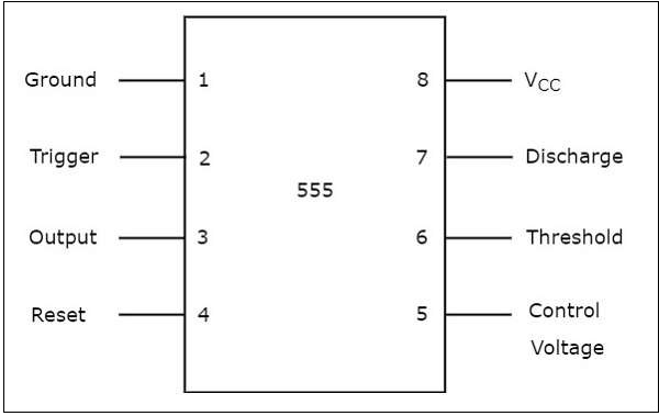
555 Timer Basics Bistable Mode from www.circuitbasics.com The 555 timer can be obtained very cheaply from pretty much any electronic retailer. There is also a selection of projects that can be built with a description of how they work. Introduction the ic 555 timer was invented in 1971 by hans camenzind at signetic corporation and it was named se or ne 555 timer. 555 signals and pinout (8 pin dip) figure 1 shows the input and output signals of the 555 timer as they are arranged around a standard 8 pin dual inline package (dip). The 555 timer is a chip that can be us… The breadboard schematic of the above circuit is shown below. Its name is derived from three 5k ohm resistors,connected in series used in it.the timer ic can produce required waveform accurately. These on off intervals can be adjusted by varying the 555 timer output and number of counter outputs.
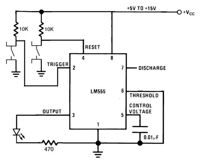
Since all three resistors are of equal value, the threshold comparator is referenced.
Find it all on ebay with fast and free shipping. With one press of the button, the led will light up, then turn off automatically after a predetermined length of time. In the time delay mode of operation, the time • adjustable. Introduction the ic 555 timer was invented in 1971 by hans camenzind at signetic corporation and it was named se or ne 555 timer. This circuit uses very basic components like 555 timer and 4017 counter. This means that the output voltage is a periodic pulse that alternates between the vcc value and 0 volts. The 555 timer delay before turn on circuit we will build is shown below. If you want to know all the pinout of the 555 timer, what each pin is and what each pin does, see 555 timer pinout. To understand the basic concept of the timer let' s first examine the timer in block form as in figure 1. In this circuit, we will connect the 555 timer to be in astable mode. 555 signals and pinout (8 pin dip) figure 1 shows the input and output signals of the 555 timer as they are arranged around a standard 8 pin dual inline package (dip). Adjustable on off timer(using 555 astable mode) in this circuit a timer with cyclic on off operations is designed. In monostable mode, the 555 timer outputs a single pulse of current for a certain length of time.
How to calculate output voltage frequency the frequency is the number of pulses per second. The 555 ic timer circuit above shows a very straightforward design where the ic 555 forms the central controlling part of the circuit. 555 timer tutorial bundle includes: The ic can operate in three different modes such as astable, monotstable and bistable, because of which it can be adapted into many types of circuit designs like time delay circuits, pulse generation circuit, oscillator circuit and much more. Adjustable on off timer(using 555 astable mode) in this circuit a timer with cyclic on off operations is designed.
555 Timer from www.tutorialspoint.com Red 5mm led or similar; There is also a selection of projects that can be built with a description of how they work. It is basically a monolithic timing circuit that produces accurate and highly stable time delays or oscillation. 555 signals and pinout (8 pin dip) figure 1 shows the input and output signals of the 555 timer as they are arranged around a standard 8 pin dual inline package (dip). 555 timer is an industrial standard ic existing from early days of ic. 555 timer monostable example circuit. The ic can operate in three different modes such as astable, monotstable and bistable, because of which it can be adapted into many types of circuit designs like time delay circuits, pulse generation circuit, oscillator circuit and much more. Daman shah june 5, 2021.
The 555 timer is a simple integrated circuit that can be used to make many different electronic circuits.
In the time delay mode of operation, the time • adjustable. It can be operated in the range of 4.5v to 15v dc supply. The 555 is also very versatile, and can be used in a variety of special or unusual applications. One of the potentiometers is tune and the other is fine tune. 555 timer was first introduced by signetics corporation in 1971 as se555/ne555. With one press of the button, the led will light up, then turn off automatically after a predetermined length of time. Free delivery on all orders over £25. Let us discuss in detail about this circuit. It can be used in led or flash lamps to turn the lamp on for a specified time. The 555 timer ic was introduced in the year 1970 by signetic corporation and gave the name se/ne 555 timer. When triggered, the timer stays on until capacitor c2 charges to 2/3 the supply voltage through resistor r3 and two potentiometers, r4 and r5. 555 timer monostable example circuit. In this tutorial we will learn how the 555 timer works, one of the most popular and.


Komentar
Posting Komentar